brad

Jan 302014
 

One of the cool things about buying a widget from Sparkfun, or Adafruit, or Pololu is that almost invariably there is some reference software posted with the product to get you off the ground immediately.

For the Sparkfun LED bargraph kit the reference code can be downloaded from the product page or directly from Sparkfun’s github repo.

The reference software comes with examples that demonstrate multiple ways of driving the LEDs. Here are a couple videos demonstrating the setup and Sparkfun’s demo code putting the bargraph breakout through it’s paces.


This is with no additional coding. Build the LED bargraph display, wire it up to the Arduino SPI, download the Sparkfun bargraph demo library, upload the example code, and sit back and watch the light show.

A different project I am working on needs a display with the feel of an analog VU style meter. I need to monitor a continuous variable and display feedback to a user of the variables relative value between it’s min and max. It was a short step from Sparkfun’s demo code to a display just like I need.

I wrote some quick demo code to read an analog input and map the read values to a set of LEDs on the bargraph display. I forked Sparkfun’s github repo for the bargraph kit and added my additional example code. You can pull the analog input to VU meter display demo from my github bargraph repo.

Here are some videos showing the setup and display of a read analog value in bar and dot modes.


This is exactly the style of display I was looking for and I think this package is going to work nicely.

Jan 282014
 

I’m in the middle of a project that would benefit from an analog style display. Something to visualize an approximate value, within a min and max range, simply and clearly.

I like to browse Sparkfun’s inventory when I’m looking for new or interesting widgets. They are hometown boys (at least if your hometown is Boulder, CO), they make a range of interesting products, and being local it is easy to order and pickup parts the same day. And it turns out Sparkfun makes a nice LED bargraph breakout kit that looks like just what I’m looking for.

Fully assembled the display is supposed to look like this
sparkfunledbargraph
The kit consists of a carrier pcb, four 8 bit serial to parallel shift registers(74HC595), some current limiting resistor packs, decoupling caps, and three 10 position LED bargraph displays. The Sparkfun kit comes with a Green, Yellow, and Red bargraph.

The Green to Yellow to Red transitions follow the typical Ok, Warning, Danger pattern. A reasonable choice by Sparkfun given no insight into their customers final designs.

When I picked up the kit I had a different application in mind. Rather than the standard transition from ok to danger I wanted more of a VU meter or power level type of display. For my application a single color for all three bargraphs makes more sense. It turns out Sparkfun sells the LED bargraphs in Blue, which is what I wanted. Each of the four colors of bargraph, Green, Yellow, Red, and Blue, are drop in replacements for the ones in the kit so you can mix and match to get the color or color ordering you want.

bargraph_blue

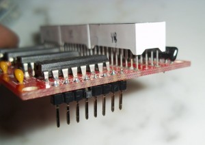
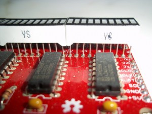
Eventually I want to mount this display in an enclosure with the LEDS showing and the pcb hidden. If the board is built as you would expect, all of the components firmly seated against the PCB before soldering, the LEDs do not sit very high above the shift register ICs. That means when the display is mounted either the enclosure walls need to be thin or else the LEDs will be set back in the enclosure wall. It turns out the LED bargraphs come from the factory with pretty long legs, probably around 5 mm. If you solder the LED bargraphs with the legs just through the PCB the front of the LEDs will stand off of the PCB about 12-13 mm and a good 6-7 mm above the ICs. That should give plenty of space to mount the PCB and have the LEDs mount flush to the front of an enclosure.

bargraph_lift1

bargraph_lift2

The kit is easy to assemble and the instructions are complete and easy to follow. The resulting display has a nice look and is easily programmed to display a variety of patterns. The kit can be assembled in under an hour and assuming you have an Arduino laying around and some jumper wires you can be displaying blinky patterns in less than 15 minutes more.

Jan 162014
 

Download and install a build environment

The Sparkfun Redbot, Pololu 3pi, and Pololu Zumo robots are all based on the Atmel atmega328p processor. All three have a wealth of libraries and supporting software. All three support at least the two most popular methods of creating code for the AVR processors, Arduino and avr-gcc (Windows and Linux). The two Pololu robots also support the Atmel Studio build environment.

Downloading and installing the Arduino environment is pretty straight forward. Download for your environment, unzip or untar, run. Not much more to it than that.

Atmel has taken over the support of the avr-gcc tool chain and hosts the builds for Windows and Linux. Installing the tool chains for Windows and Linux are documented on the Atmel site.

Get the supporting libraries

All three robots have additional supporting libraries; Arduino style for the Redbot and Zumo, Arduino, Atmel Studio, and straight avr-gcc style for the 3pi. Both vendors, Sparkfun and Pololu, provide links to download their libraries. Pololu supplies prebuilt installers for different versions of their libraries. Both companies also provide source on Github; Redbot / Zumo / 3pi. For the Zumo you want both the Zumo Shield library for Arduino programming and the libpololu-avr library for direct avr-gcc programming.

I prefer to go straight to the source and download the libraries fresh from Github. All of the libraries provide a “Download Zip” link to download a compressed bundle straight to your desktop. After you have the downloaded bundle you can uncompress and install it. I prefer to use GIT directly, under Windows and Linux, and clone the repositories directly to my desktop. Whichever method you use you will eventually have copy of the libraries on your local machine.

To clone the repositories locally under Windows I use the git bash shell from git-scm, under Linux I use git. If git is not installed on your flavor of Linux use your distro’s package manager to download and install it.

Install the libraries

The Redbot and Zumo Arduino libraries need to be installed where the Arduino environment can see them. Arduino provides tutorials on installing 3rd party libraries so I wont repeat that information here. Pololu also provides ample documentation on installing their libraries, for all three environments, Atmel Studio, Arduino, and raw avr-gcc.

For the Pololu 3pi robot I am using raw avr-gcc. The steps I used to install the Pololu libpololu-avr library are:

1 ) Insure you have the avr-gcc tools installed

From a command line run avr-gcc –version
If the program is found move forward, if not, return to installing the avr-gcc tool suite.

2 ) Build the Pololu Library

The Pololu library make file by default builds all of the flavors of AVR libraries for all of the Pololu products that use the library. For the 3pi you only need support for the 168 and 328p libraries.

New 3pi robots are based on the Atmel AVR 328p processor. Older 3pi robots were based on the 168 processor. The example program makefiles still reference the 168 library. At this point it is easiest to keep both the 168 and 328 libraries. Over time it makes sense to migrate to the 328, if you have a newer 3pi robot, but for the sake of expediency build both libraries for now.

Edit the libpololu-avr/Makefile and remove the building and installing of unneeded libraries.

makefilemod

In a command window in the libpololu-avr directory make the libpololu libraries. Simply type make in the libpololu-avr directory. The build process should eventually yield two files called libpololu_atmega168.a and libpololu_atmega328p.a. These are the 168 and 328p libraries containing the functionality provided by the Pololu library.

3 ) Copy the libraries and include files

Next you need to make the libraries and required include files visible to avr-gcc. You can either modify the example make files as you create or re-use code to point to your local versions of the pololu libraries and include files or you can copy the library and include files to the avr-gcc default path. Pololu recommends copying the files into the avr-gcc path.

See the pololu/libpololu-avr/README.txt file:

== Manual installation ==

If you have the source repository of the library instead of a binary
distribution, you will need to build the library (.a) files by running
"make" and also copy all the files in the "src" subfolder into the
"pololu" subfolder.

Next, copy libpololu_*.a into your avr-gcc "lib" subfolder.

Finally, copy the entire "pololu" subfolder into your avr-gcc
"include" subfolder.

You are now ready to use the Pololu AVR library.

Use the make show_prefix to discover the avr-gcc paths used in your install.

show_prefix

– Copy the library files, libpololu_atmega168.a and libpololu_atmega328p.a, into the avr-gcc lib directory.
– Copy the pololu directory, libpololu-avr/pololu, not just the files in pololu, the pololu directory and the contained files, into your avr-gcc include directory.
– Copy the contents, including any sub-directories, of the libpololu-avr/src directory, into the newly copied pololu directory in your avr-gcc/include path. In this case copy the “contents” of the src directory, not the src directory itself, into the avr-gcc/include/pololu directory.

Test your install and build the demo code

If all of the above worked you should be able to change into the libpololu-avr/examples_templates/3pi-demo-program and type make.
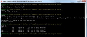
make3pidemo

Now that you have a hex file you need to upload it to your robot.

I use avrdude directly from a command line. Using the Pololu AVR programmer the command looks like:
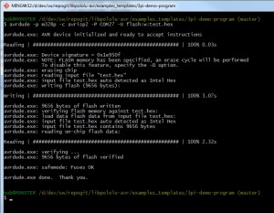
upload3pidemo

If everything worked cleanly you should have a fully functioning build and deployment environment ready to write new code.

Jan 132014
 

Insuring that the intake and exhaust valves are closed in each cylinder before working on that cylinder requires turning the engine over by hand. I assume anyone doing major work on an in vehicle engine knows enough to disconnect the battery and the fuel before crawling around under the hood. If you don’t maybe someone else should be working on your ride.

As I mentioned in an earlier post it is critical the intake and exhaust valves are closed before any work is done on the spark plug wells.

When the valves are open on the Triton 6.8L V10 the edges of the valves intersect the line of the spark plug wells.

Valve visible through spark plug hole

Valve visible through spark plug hole

Valve visible through spark plug hole

Valve visible through spark plug hole

The Timesert reamer, tap, and setter fill the spark plug well and could chip, break, or bend a valve if the tool was inserted into a spark plug and struck an open valve.

Any damage to a valve means removing the heads and replacing the valve. A simple over the fender thread job gone horribly wrong.

Reaming and tapping generates abundant chips. Even using grease in the flutes to catch as many chips as possible I still ended up with chips down in the cylinder.

Tap coated with grease

Tap coated with grease

Reamer packed with chips

Reamer packed with chips

Aluminum cuttings inside of the cylinder.

524A8C79_chips

524A892B_chiips

You want to get the chips out of the cylinder before running the engine. If you blow the chips out with pressurized air, which works pretty well, you don’t want to get chips up into the intake where they will just be sucked back into the cylinder the first time you start the engine.

The bottom line is you want to get the valves closed before doing any work on that cylinder.

To confirm that the valves are closed Timesert recommends taking the valve covers off and checking that the rockers are not pressing the valves open. That sounds like work and mess I don’t want if it can be avoided.

While I wasn’t a fan of the Calvan kit for placing the inserts, see my previous post, Calvan does have a pretty slick way of determining if the valves are closed. With the valves closed the cylinder should hold compression, it should be “mostly” air tight. If the cylinder holds pressure the valves are closed. If either valve is open, intake or exhaust, the cylinder will not hold pressure. The Calvan kit comes with a trick little piece of hardware, which luckily can be purchased separately, that allows you to check that the cylinder is air tight through the spark plug hole.

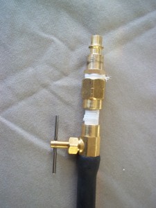
Calvan valve checking tool

Calvan valve checking tool

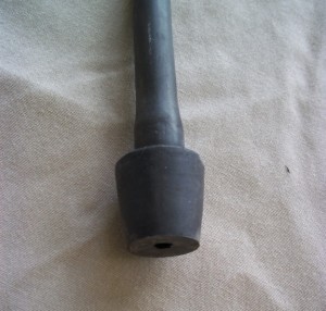
stopper

petcock

With the spark plug removed you jam the rubber plug into the spark plug well creating a pretty much air tight seal between the rubber stopper and the well. Next close the small petcock on the other end of the tool and hook up a compressor to the compressor nipple. Slowly open the petcock and begin pressurizing the cylinder. If the valves are open, even a little bit, you can hear air escaping from the cylinder and the rubber stopper will remain seated. If the valves are fully closed the cylinder will pressure up and blow the rubber stopper out of the spark plug well.

The steps to check that the valves are closed are:

1. Hook up an air compressor to the tool
2. Jam the stopper into the spark plug well
3. Open the petcock and listen for air escaping from the cylinder
4. Slowly turn the engine over by hand using an 18 mm socket on the front of the crankshaft
5. Keep turning the engine until the valves close causing the cylinder to pressurize and blow the rubber stopper out of the spark plug well.

After all of that to make sure the valves are closed you need to make sure the piston is down. The piston rises up far enough in the cylinder for the insert tools to impact the top of the piston. After insuring the valves are closed I use a bamboo skewer through the spark plug hole to measure the depth to the piston and make sure there is plenty of clearance between the head and the piston.

To see some video of the Calvan tool in action check out these videos

Jan 092014
 

I’ve always been interested in competitive robotics. Two (or more) robots duking it out on the field of honor. Trying to solve a problem as fast or efficiently as possible, all the while trying to avoid, out score, or destroy the competitions robot.

Competitive robotics can generally be divided into to groups, direct combative and competitive problem solving. Both are a lot of fun, although combative can get pretty ugly, and expensive, in a hurry.

Competitive robotics puts a lot of pressure on developers and implementers to find optimal solutions in unstructured environments where other participants are actively trying to out score, block, or destroy your robot. You often need to come up with ad-hoc solutions in the middle of competitions to account for variations in the environment and to counter competitors robots.

Things we’ve had to overcome include changes in playing field surface, broken parts, changes in starting conditions, changes in competition rules that you don’t find out about until you get to the competition, and as always, differences in competitors robots that require you to adapt and modify your strategies on the fly.

In competitive robotics you push, pull, climb, and race to get the task at hand done before your competitor does. Changes in traction on different fields requires adapting your motion platform’s drive system. You can change your wheels, from slicks to diggers, or the other way round. Sometimes simply cleaning the tires, washing the dust and dirt off, improves traction enough to make a difference. Sometimes you need more. We’ve created studded tires by lacing plastic wire ties around the wheel and tire and cutting off the tails to leave the knobs pointing out. You do what you have to do to keep your robot moving and stop the competitors robot from moving.

Broken parts are always a bane. Hopefully you’ve built your robot to be maintainable. Motors die, drivers burn out, axles twist and break, screws fall out and pieces fall off. Broken parts require more an act of Nascar like pit crew skills than design changes. How fast can you swap out or adapt parts, under pressure in the middle of a competition, while maintaining a competitive robot. Sometimes you just work around the broken part, changing code to not use the broken functionality or adapting other sensors or actuators to try to work around the broken parts.

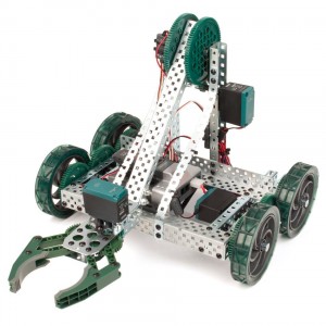
The four robot platforms I’m actively using are the

IFI Vex Robotics line,
clawbot

Pololu’s Zumo Mini Sumo bot,
zumo

Pololu’s 3Pi,
3pi

and Sparkfun’s Redbot.
redbot

All of these platforms are extensible in various ways. Each of them have varying degrees of physical reconfigurability, with the VEX robot being the most physically reconfigurable, the Redbot next, then a toss up between the 3Pi and the Zumo (at the level of not much). All four platforms support adding sensors and of course full reprogrammability. The 3Pi, Zumo, and Redbot benefit from having the same microcontroller, the Atmel Atmega328p, and the same programming environment, Arduino or avr-gcc. The VEX controller is based on an ARM Cortex controller and uses the quite capable (but not free) RobotC development environment.

The VEX ARM processor arguably provides a much more powerful computing platform but is a more closed environment. The Redbot was designed to be modified with multiple sensor and actuator mount points and a fully open design. The 3Pi and Zumo have an open software development environment but suffer from a more closed hardware platform. Both the Zumo and 3Pi robots are able to be extended physically but not as simply as the Redbot or VEX robots.

The VEX robot, while powerful and benefiting from a reasonable line of accessories, is pretty much closed. The manufacturer, IFI, provides scant documentation on the VEX controller internals.

Each platform has different strengths and weaknesses.

The VEX line is expensive and relatively closed. The platform is physically very reconfigurable and being targeted at middle and high school students is pretty robust. The IFI provided sensors are mechanically robust and easy to interface. The downside of being targeted at students is the platform is not easily extended. IFI / RobotC provide few opportunities to step outside the bounds of the RobotC development environment. The upside is, it is harder for a student to get too far afield. The downside is, it is harder for a student to bring new innovations to the platform.

The Redbot line is fully open and extensible. The schematics, board layouts, and platform components are open and documented on Sparkfun’s website. The Redbot is probably the least robust physically. The Redbot is a great development platform but with an eye towards high extensibility and low cost it is probably at the highest risk of taking a catastrophic hit in a competition. That said the Redbot might be the best price to performance platform of the four. The Redbot’s size makes it too big to qualify for mini sumo competitions.

The 3Pi platform is hands down the best choice for line following competitions. It is pretty much designed to be fast and excel at line following. The 3Pi is low to the ground, is probably the fastest by far of the four robots mentioned here, and has a built in integrated line sensing array. The 3Pi platform provides for some extensibility. The 3Pi can be readily extended with sensors and other electronics but the motion platform is pretty fixed. Pololu sells a prototyping shield for adding sensors and other electronics. They also sell replacement motors with different gear ratios to achieve different speed to torque characteristics, but that is about it. Two wheel pivot steering with a caster is pretty much all you get. The 3Pi also requires a pretty clean and unobstructed field. The wheels are on the smaller side and not made for climbing or rough surfaces. If you are doing line following, maze solving, swarm bots, stuff that relies mostly on interesting software solutions and limited environmental interactions the 3Pi is the way to go.

The final robot I actively use is the Pololu Zumo. This bot is specifically a mini sumo pusher bot. Like the 3Pi, the Zumo is optimized for mini sumo competitions. Like the 3Pi the physical platform is not readily extended. The mini sumo rules limit the weight and footprint of the bot, so large physical changes to the bot are probably not in the cards anyhow. The Zumo allows for some sensor extension but the base platform with the sensor array consumes most of the available IO of the 328p microcontroller. Like the 3Pi the motors can be changed to achieve different gear ratios. Also similar to the 3Pi the Zumo relies on two motor slip skid steering. The Zumo is a tracked platform and has a pretty good grip but again like the 3Pi it requires a relatively smooth obstruction free playing field.

Each of these robots solves a different problem in a different way. For line following competitions and newer roboticists the 3Pi is the way to go. For mini sumo the Zumo is great platform. For the home hobbyist the Redbot is probably the best answer. For a more physically extensible and more powerful (and significantly more costly) platform the VEX line is the way to go.

In the end all of the robots are great solutions each with it’s individual strengths and weaknesses. Pick the one that best fits your style or target competition and go for it!

Here’s hoping to see your robot on the competition field.

Jan 082014
 

Here is the original blog post over at Lumberjocks.com

Nightstand 5

Even though I clamped and cauled the top and shelf during the glue up there was still a slight offset between the panels, maybe around a 64th or so, maybe a little less.

I machine planed the panels before the glue up so the panels were pretty flat and reasonably smooth.

I like the tactile quality of a planed surface more so than a sanded surface so the offset and the desired for a planed finish combined to lead me to hand plane the finished top.

Hand planing the top turned out to be a bigger hassle than I anticipated. There was a low spot in the middle along the glue line so more planing was required than I hoped for going in. The grain reverses in multiple places so tear out was a problem. I ended up planing mostly cross grain with a jack to flatten the panel. I followed up with a smoother using a 50 degree blade (pretty high angle) and the smallest mouth opening / cut I could make. I tried heavier cuts and lower angle blades but I would get tear out every time. That was with freshly honed blades sharp enough to shave with.

The result of the high angle blade and the infinitesimal cuts was a surface smooth as glass with no tear out but it took a LOT of passes. I mean a LOT. Here’s one pile of shavings from smoothing one side. You could pick pretty much any one of these shaving and see through it, they were all that fine. I made about three piles of shavings like this and didn’t reduce the thickness of the top or shelf by more than a 32nd. These were a pile of wispy shavings.

Here’s how the shelf looked almost done. You can still see some of the plane marks but most of the tear out was cleaned up by now.

Here’s the top finished.

Jan 082014
 

Here is the original blog post over at Lumberjocks.com

Nightstand 4

After milling up the pieces and parts it was time to begin cutting to size and fitting up. The construction is all mortise and tenon and sliding panel. At this point the pieces are still marked with the position identifier and the orientation. I use kids sidewalk chalk to mark the pieces. Sidewalk chalk comes in different colors to mark light or dark wood, it’s dirt cheap, large sticks so it’s easy to find and handle, and it wipes off clean with a little elbow grease and a rag.


I had to tune up the panels to get them to fit snug but not too tight. A couple swipes with the shoulder plane and then run around them with a block plane to break the corners.