brad

Dec 312013
 

The Arduino Pro comes with a bootloader installed, meaning it is plug and play ready to work with the Arduino environment. All you need is a way to hook it up to upload new firmware.

The Pro is a stripped down version of the Arduino UNO. One of the stripped parts is the USB to serial programming interface. Programming the Pro requires either an ISP programmer or a USB to serial translator.

The Pro brings out the standard green to black FTDI cable programming header and Sparkfun recommends their FTDI programming cable (5V) for a plug and play experience. That is all well and good but a FTDI cable is pushing a cost of $20 USD (Sparkfun’s 5V and Adafruits 3.3V). You can buy FTDI breakout boards with the same pinout for a little less, around $15 USD (Sparkfun, Adafruit). That’s better than $20 but still more than twice the cost of other options.

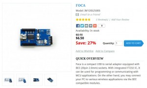
If you are willing to wait for the shipping from China (or you order ahead) you can get a FTDI breakout for less than half the price of the Sparkfun or Adafruit breakouts. The iTeadStudio FOCA breakout has a couple of nice features over the Sparkfun and Adafruit breakouts, and one glaring hassle. First the good, the FOCA interfaces with either 5V or 3.3V systems with the flick of a switch. The FOCA also has an XBEE footprint allowing it to be used as a USB to XBEE interface (compare to Sparkfun’s USB to XBEE board at $25). All in all a pretty nice package for $6.50 USD (as of Dec 2013).

iTeadStudio FOCA

iTeadStudio FOCA

Now for the hassle part. The pinout of the FOCA is NOT a direct crossover to the “standard” green to black programming pinout on Sparfun’s and Adafruit’s FTDI cables, and of course the pinout on the Arduino Pro.

The pinout on the Pro is green to black being reset/dtr, TX, RX, power, cts, gnd.

Sparkfun Arduino Pro

Sparkfun Arduino Pro

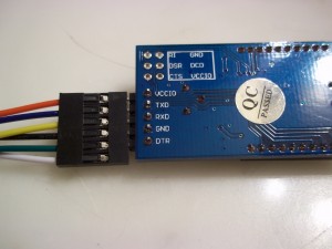
The pinout on the FOCA is power, TX, RX, gnd, dtr/reset. Not a straight across plug and play.

FOCA Pinout

FOCA Pinout

Fortunately for half the price it is pretty easy to make an adapter cable. I happened to have a 6 pin to 6 pin inline cable with crimped on connectors which made it easy to move the pins around.

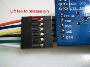
The pins are held in place by little plastic fingers that can be easily lifted back with the tip of an Xacto knife or dental pick, allowing each pin to be slid out of the connector and moved to a different position.

lifttab

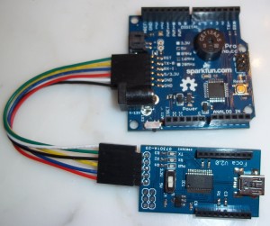
A quick shuffling of both ends of the connector, to move green to one end and black to the other end on the Pro side, and to line up power, gnd, TX, RX, and reset on the FOCA side and wa-la, a FTDI programmer for under $7.50.

focatopro

Dec 292013
 

I picked up an Arduino Pro from Sparkfun during their cyber monday sale. The Pro is a stripped down version of an Arduino UNO for about half to a third the price. It is missing quite a few features so if you are just starting out a standard Arduino is probably a safer bet. If Arduinos are old hat the price point is pretty attractive, I picked mine up for just under $9 USD.

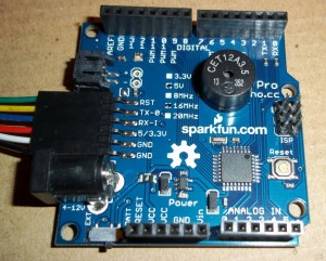
The Sparkfun Pro has a round footprint in the middle of the board that turns out to be meant for installation of a buzzer, specifically the Sparkfun 12mm Buzzer. This little buzzer drops right onto the board, but other than a comment from Sparkfunion Robert there is no documentation on how to mount or use the buzzer.

It turns out the Buzzer recommended is really a tiny speaker. A mag coil driving a tiny disk. The two pins connected to the mounting holes connect to the Arduino digital pins 4 and 5. It doesn’t seem to matter which direction you mount the buzzer. I happened to mount the buzzer with the words arbitrarily “up”, which resulted in the “+” side of the buzzer “down”. Down being connected to D4 and Up connected to D5.

Sparkfun Arduino Pro

Sparkfun Arduino Pro

Driving the buzzer is relatively simple, you just set one of the pins, D4 or D5, to an output, pinMode(4,OUTPUT) or pinMode(5,OUTPUT), and drive the other pin, 4 or 5, with a changing signal. The recommended buzzer is basically a speaker and so the input needs to be modulated to generate a sound.

The simplest code to generate a 1 second, 1 KHz tone is:


void setup()
{
pinMode(5,OUTPUT);
tone(4, 1000, 1000);
}
void loop()
{
}

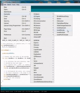
The built in Arduino example toneMelody can be easily modified to play out the buzzer.

First open the toneMelody example:

Arduino toneMelody

Arduino toneMelody

Modify the bolded lines and upload the sketch to the Pro:

==========================================================================


#include "pitches.h"

// notes in the melody:
int melody[] = {
NOTE_C4, NOTE_G3,NOTE_G3, NOTE_A3, NOTE_G3,0, NOTE_B3, NOTE_C4};

// note durations: 4 = quarter note, 8 = eighth note, etc.:
int noteDurations[] = {
4, 8, 8, 4,4,4,4,4 };

void setup() {

pinMode(5,OUTPUT); // set the "other" buzzer pin to an output

// iterate over the notes of the melody:
for (int thisNote = 0; thisNote < 8; thisNote++) { // to calculate the note duration, take one second // divided by the note type. //e.g. quarter note = 1000 / 4, eighth note = 1000/8, etc. int noteDuration = 1000/noteDurations[thisNote]; tone(4, melody[thisNote],noteDuration); // output the tone on the "+" pin

// to distinguish the notes, set a minimum time between them.
// the note's duration + 30% seems to work well:
int pauseBetweenNotes = noteDuration * 1.30;
delay(pauseBetweenNotes);
// stop the tone playing:

noTone(4); // turn off the tone
}
}

void loop() {
// no need to repeat the melody.
}

==========================================================================

The Arduino Pro buzzer playing the toneMelody example sounds like this:

Dec 122013
 

It turns out somewhere along the way Ford changed the head design on the Triton and changed the way the spark plugs seat in the head. This affects how the insert tools cut, or don’t cut, the seats for the insert.

You can read the Timesert paper on the issue here here

I posted a video of my heads here

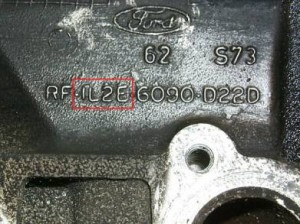
According to Timesert the problem heads have the casting mark with a 1L2E in the casting number.

PROBLEM HEAD

12LE_casting

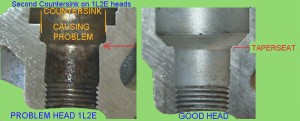
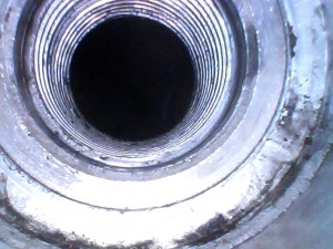
The problem heads have a step which prevents the seat cutting tool from registering properly in some insert kits.

romeo2

The casting mark on the heads of my truck look like this

FordF250EngineCasting 009inv

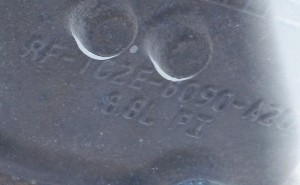
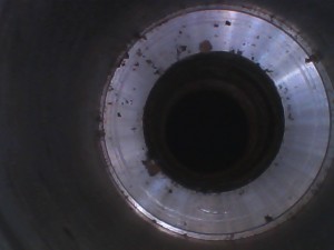
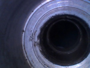
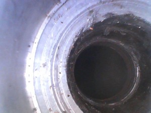
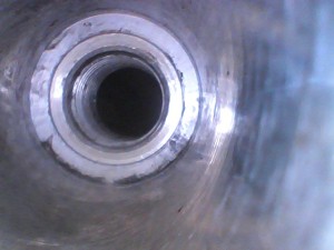
I blew up the image and inverted the color so I could see the numbers better. No 1L2E on my heads. Looking down the spark plug hole with a bore scope on a fresh, uncut spark plug well shows a smooth sloped transition from the well wall to the spark plug hole.

52491E5F

It turns out the Timesert kit I purchased, the 5553, accommodates both head styles, but it’s nice to know what you’re working with before you start cutting.

Dec 102013
 

It’s been a while since I updated the status on putting inserts into my Ford Triton V10 aluminum engine head. Since my last post in this series I’ve installed inserts in all 10 cylinders, created a series of videos on the process, and driven a couple hundred miles on the newly inserted heads. All in all the process was relatively pain free, no major FUBARS, and the truck seems to be running great. We’ll see when I put a heavy load on the engine or get a few thousand miles, but so far all seems well.

I’ve uploaded the videos of the process to Youtube and linked them here.

F250 Triton Timesert spark plug blowout repair Youtube playlist

Dec 102013
 

Here are the images of the inside of the cylinders at different stages of tapping and cleaning.

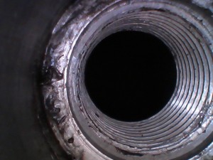
With the valves open and the original spark plug seats and threads:

In these first two images you can see the edge of the valves. Hitting one of these with the cutter would be catastrophic and require a head removal and valve replacement.

5248EC4A_valveedge

5248ECB6_valveedge

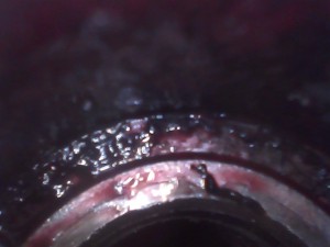
Here are a couple pictures of the original spark plug threads. You see the wells are only threaded part way.

5248ECA9_4threads

5248FF22_4threads

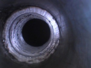
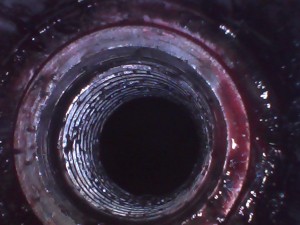
Here are some pictures of the tapped spark plug holes cleaned and waiting for the inserts:

52523D1B_tapped

525228CE_tapped

525253A3_tapped

524B624E_tapped

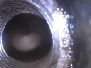
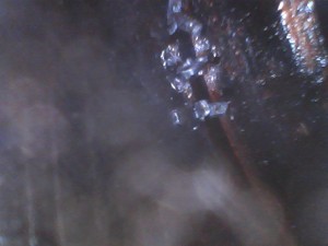
Here are some images of the tap cuttings down in the cylinders. These all need to be cleaned out 100% before installing the inserts. The tapped holes are quite a bit bigger than the inserted spark plug holes so it’s best to get the chips out while you have more room to insert a blower or a vacuuming hose.

524A8C79_chips

524A892B_chiips

524A8911_chips

524BCEC9_chips

524A8C37_chips

Here are some pictures after cleaning, blowing and vacuuming the cylinders:

524BD3A0_chipsclean

524BD23A_chipsclean

524BD25A_chipsclean

524BD264_chipsclean

In the following images you can see the insert after it is installed, seated, set, and loctited in place. You can see the new bevel for the spark plug seat in the center of the insert. The first two images show I used a bit too much loctite on this cylinder. I cleaned up the excess loctite and let the heads sit for a few days after installing the inserts and before putting in the new sparkplugs. The last two images are how each hole looked after I installed a new insert.

52491AE5_inserted

52491B9A_inserted

52522EEF_insert

52522F15_insert

Sep 282013
 

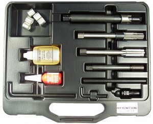
Why the cost difference and what do you get for your money. Looking at the two kits the most obvious differences are that the 5553 comes with 5 inserts, some oil and loctite, and a few extra tools.

4412E 5553
14mmSPkit01 Tritonkit5553

Is a small bottle of oil, some loctite, and a couple of “convenience” tools worth a couple hundred bucks to you, maybe, maybe not. The 5553 kit comes with 5 inserts but if you only need one, or if you want the full thread inserts, maybe those 5 inserts don’t add any value. The inserts are normally around $11 each, so if you need all 5 the 4412E is going to cost you another $55 on top of the $200.

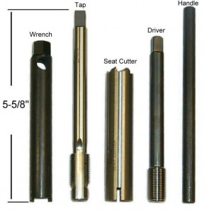
Besides the inserts the 5553 sports a different seat cutter, adds a reamer to size the hole before tapping, adds a seating tool, and comes with a blown molded case to keep all the pieces organized.

The steps to cut, tap, and insert the hole are different between the 4412E and 5553 kits. With the 4412E kit you ream and tap the hole in a single operation, you then thread the tap deep into the newly cut spark plug hole, drop the seat cutter down over the tap and cut the seat, remove the seat cutter and tap, thread the insert on the insert setting tool, screw the insert into the newly tapped hole and seat and set the insert in one operation. With the 5553 kit you cut the seat, ream the hole, tap the hole, seat the insert, then set the insert, all as separate operations.

With the 4412E kit you perform more operations overlapped or without removing a tool between a job. This sounds like it could be faster but it also sounds less flexible. I wanted more tools, each with a specific job so I could do each step, make sure each step was correct, and then move on to the next step.

I did not like the method of seating and setting the insert in one operation with the 4412E kit. With the 4412E kit you thread the insert onto the setting tool, use the setting tool to seat the insert, and then continue tightening eventually setting the insert.

Seating the insert means making sure the insert is tightly screwed and seated into the tapped hole.

Setting the insert means mechanically expanding the bottom of the insert and camming the locking pin to lock the insert into the hole. With the 4412E kit the assumption is the seating torque is significantly less than the setting torque. Otherwise the insert would start to set before it was fully seated.

With the 5553 kit the seating tool is separate from the setting tool. The insert is first seated with a short threaded tool and then set with a long threaded tool. The seating tool has short enough threads to insure it does not reach the bottom of the insert where the swagging and camming occur. The insert is first fully seated with the seating tool and then followed with the setting tool. That way there is no chance of partially setting the insert while trying to seat it.

The 5553 seat cutter looks a bit nicer in that the seat cutter works stand alone whereas the seat cutter in the 4412E kit slides down over the tap after you’ve tapped the hole.

All in all the 5553 kit seems more complete and makes more sense to me. The 5553 kit is quite a bit more expensive than the 4412E kit and breaks what are single steps using the 4412E kit into multiple steps.

If you’re a professional mechanic, where time is money and you’re always working on someone else’s vehicle, maybe the 4412E kit is a better choice, get ’em in and get ’em out.

I’m not in a hurry and I’d rather take my time with each step.

Sep 122013
 

Ok, so I know I have a blown spark plug. I found the ignition coil and plug rolling around on top of the head, instead of in the plug well where they belong. It’s pretty obvious what the problem is. The next question is, what do I do to fix it.

Doing a bit of web searching for blow spark plug or spark plug repair will turn up more hits than you can count, for many different engines. This problem is clearly not just a Ford Triton problem.

Ok, so it’s a common enough problem, but what do you do to fix it. Looking at what others have done it looks like solutions range from replacing the entire engine to just screwing the plug back in, and everything in between. People have reported replacing engines at a cost for the Triton 5.4 and 6.8 for anywhere between $6,000 and $12,000. Ok that’s clearly out. That’s going to be more than I paid for the entire truck, there’s no way I’m paying that kind of money for a repair. And there’s no reason I can see that this requires a new engine.

Next, new heads. It sounds like if you go to Ford they are going to suggest new heads. Replacing the heads means lifting the cab off the frame, stripping all the top end plumbing, new fluids, etc. Reports are $2,000 to $4,000 for head replacement. And it’s not clear that you get a solution any better than what you started with. Four threads in an aluminum head. It might hold until the next time you replace the plugs, or it might not. I’m not really interested in spending that kind of money to replace a weak head with another copy of the same weak head.

New engine and new heads are out for me. Too much money and both sound like overkill. The next solution is a threaded insert. First off, what is a threaded insert? Time to check wikipedia. A threaded insert is a threaded cylinder often placed in a softer base material to provide new or stronger threads for a fastener to thread into.

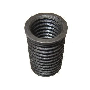
Here’s a picture of a typical threaded insert:

insert

Inserts come in a variety of sizes and shapes but they all have the feature of some way to screw / glue / press fit / or somehow otherwise afix themselves into a hole in the base material or the material being repaired, and provide an inner threaded hole for the new fastener to screw into. In my case the outside of the insert needs to attach itself to the spark plug hole in the head and provide new threads for the spark plug to screw into.

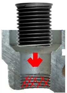
Looking back at the cross section of the cylinder head cut through the plug hole, assume you’ve just blow a spark plug. Assume all of the threads have been ripped out of the plug hole and you’re left with essentially a smooth hole top to bottom with nothing for the spark plug to screw into.

plugholewreckedthreads

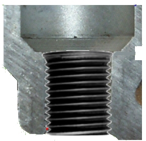
The basic idea is to get the threaded insert fixed into the spark plug hole resulting new threads for the spark plug to screw into.

insertIntoHole insertIntoHole

Ok, so that’s what a threaded insert is, but are they any good. Is a threaded insert a good fix? And what’s it going to cost to put one in? This is where things get complicated. There are many many options for threaded inserts, different materials, different sizes, different ways to fix them in the hole. The question is which solution is best, and what’s it going to cost. Searching the web for Triton, or V10, or 6.8L, spark plug repair, then filtering out the broken plug problem in the 05’s and later, and the solutions narrow down to just a handful. It turns out this is a common enough problem you can stop by your local auto parts store and buy a cheap spark plug thread insert kit for $40 to $60 bucks. You can also get mid range insert kits for in the $130 to $200 range, and then you can get the “high end” kits for around $400. Ok, so what gives, why the huge range in prices, 10 to 1 from the cheap auto parts kit to a high end kit. At this point you’re going to have to rely on a lot of anecdotal evidence, people’s opinions, and marketing literature.

Opinions vary widely on the reliability of using thread inserts but the majority seem to lean toward “a good insert is a good fix” and “a bad insert is no fix at all”.

Ok, so it sounds like a “good” insert is a reasonable, reliable, fix. Now what is that going to cost. Again, searching the web reveals people quoting hundreds to thousands to get an insert put into a head. It looks like there are two schools of thought, the “remove the head and do it right” school, and the “do it over the fender with the heads in place” school. What this means is option 1, removing the heads, is going to cost an arm and a leg. Getting the heads off of the Triton V10 is a labor intensive job, that means expensive. I understand that having the heads off allows you to see exactly what you are doing, where the tap is, how deep the insert goes. With the heads off you can insure clearance between the tools and the valves, but it’s expensive. I’d like to avoid expensive. The “do it over the fender” route is the cheapest, as long as nothing goes wrong. But even if something does go wrong it’s probably not that much more expensive than going the “remove the heads” route in the first place. So now I’m headed down the “do it over the fender” threaded insert path. So what does that cost. It looks like you can get a “trained” mechanic to do an over the fender thread insert for anywhere from around $500 to nearly $1000 for the first insert and something less for the second and third insert if other plug holes need inserts at the same time. Five hundred to a thousand bucks is still not cheap for a single plug hole repair.

How about if I do it myself. Now I’m down to the cost of the insert kit and my time. Starting at the low end, with the cheap kits, the heli-coils and other spring like thread insert variants. The heli-coil style inserts are pretty much universally panned. The opinions seem to be that heli-coils in a spark plug hole are a waste of time, it will come out again. So that’s no good for me. I may be cheap but I don’t want to do this job again.

As you start to narrow down the kits a few big names start to stand out, Timesert seems to be by far the most popular and most recommended. After Timesert you hear less often about the Cal-Van Tools kit, Lisle Spark Plug Rethreading tool for Ford – 65900 kit, and a small handful of others. All three of these “high end” kits work by the same principle, drill out the existing spark plug hole to make room for the new insert, tap the new hole for the insert to thread into, and then “lock” the insert into place one way or another.

The Lisle immediately turned me off by requiring the top of the insert be deformed with hammer blows from above after the insert is screwed into place. You drill out the spark plug hole, thread it, put in the insert, then drop a cone shaped tool on top of the insert and beat on it with a hammer to expand the top of the insert and lock it into the head. Something about that just sits wrong with me. It looks like people have used the Lisle solution and are happy. I think I’ll pass.

The Cal-Van kit gets some nice reviews. Apparently the Cal-Van kit is what Snapon sells for thread repair, Snapon – Set, Spark Plug Insert Installer, Ford. So if it’s good enough for Snapon it ought to be good enough for me right? Yeah, not so much. I’m not a tool fanboy. I like high quality tools but just because it has someone’s name on it doesn’t mean it’s a good tool. I like to research my tools and make my own decisions. Looking at the Cal-Van it has one trick I really like, but one another trick that makes it a show stopper for me. I’ll talk about the bad first so I can explain why I ruled out the Cal-Van. The Cal-Van insert is touted as one of the largest inserts you can buy. By largest I mean the outside diameter. The inside diameter of all of the inserts has to be the same size, the size of the spark plug. The outside diameter can vary depending on the size of the hole drilled in the head. The advantage to a mechanic of using the Cal-Van insert is that it is so big that the hole drilled in the head will hide all previous evils. That is, if an attempt has been made previously to repair the spark plug hole with a smaller insert the Cal-Van insert is so big you just drill out everything, wider and bigger than any insert that has come before. The Cal-Van is the final solution. Great big hole, drill away all that have come before. This sounds good if you’re a mechanic on the clock. You don’t want to mess around finding the right size insert depending on if this plug hole has been repaired before or not. Just drill it out to the maximum size and put in the insert. This might sound good but it’s a non starter for me. I’m more a take just enough off to do the job right, and no more, kind if a guy. Given that the Cal-Van is final solution, and I’m not quite ready for a final solution, I decided to pass on the Cal-Van. Cal-Van does have a neat trick for determining if the valves are closed before attempting the repair. I ended up buying that piece of their kit but I’ll talk about that later.

That brings me to the Timesert kit. Timesert makes a couple kits to repair Triton plug blowouts, the 4412E and the 5553. At this time the 4412E costs around $200 plus the cost of the inserts and the 5553 costs around $400, is a bigger kit, and comes with 5 inserts. Timesert also sells a 4412 kit, without the E on the end. If you are working on a Ford Triton you want the 4412E kit, not the standard 4412. The E stands for Extended, as in longer tools. The Triton spark plug wells are nearly 6 inches deep. You need the extended tools to reach.

In my next post I’ll talk more about the Timesert kits and which kit I purchased.

Sep 082013
 

Searching online for Ford Triton blow spark plug issues will immediately turn up a dismaying number of links. I did a little bit of research before buying the V10 and I knew a blown plug was a risk for this engine. Actually a blown plug is a risk for any engine, aluminum head engines in particular, and the pre-2003 (2002 and earlier) Triton engines even more so.

Ford engineers in their not so infinite wisdom decided 4 threads in an aluminum head was more than enough for any spark plug. I wouldn’t be surprised to find that 4 threads are enough if you calculate the thread size, the shear strength of the aluminum threads, the cylinder pressure against the spark plug cross section, etc. Four threads are probably plenty strong enough. I personally don’t believe 4 threads are the cause of the failure, but I do believe 4 threads are what lead to the failure.

Here’s a picture snatched from timesert.com showing a cross section of the Triton head through the spark plug hole. As you can see, not a lot of threads for the plug to hold onto.

plughole4threads

Four thread are probably fine for holding against engine compression, but 4 threads are probably not fine for holding against thread shear when installing plugs. I suspect the blowout problem stems from over torquing the spark plugs during install, at the factory or during plug replacement. It’s pretty easy to see that screwing a steel spark plug into an aluminum hole is going to be at risk of shearing out the aluminum threads.

If you read the stories it seems like the vast majority of spark plug blowouts occur after a plug change. Notice in the previous post I mentioned I bought this truck from a mechanic who told me he had replaced the plugs. I know there are plenty of reports of plug blowouts on new engines that have never had the plugs replaced, but it does seem more likely to happen after a plug change.

This seems consistent to me with thread shear (thread pull out) caused by over torquing during install. Ford must have thought so too because early on after plug blowouts starting being reported Ford issued a service bulletin specifying spark plug torque during install. I understand there is controversy about whether over torquing is an issue or not. The guy at blowoutsparkplug.com seems to think over torquing is not an issue, that the issue starts with “a plug coming lose for some reason. After the plug becomes a little loose the plug starts to rattle in the treads and works the aluminum until the treads give out.”. I’m not sure I buy that, but hey, pick your poison. I’ve screwed enough steel bolts into aluminum to know that if you’re not careful you can pull the treads out in a heatbeat.

So what do I mean that 4 threads are not a problem, but really are the problem? I think 4 threads probably are fine in terms of holding strength but I also think 4 threads are not near enough to prevent thread shear during install. With more threads you might have more holding power than needed for running, BUT, you also have more thread shear strength to withstand the gorilla manhandling that happens during plug install.

So it’s still up in the air to me whether Ford is to blame, the technicians are to blame, or the shade tree mechanics swapping plugs on a Sunday afternoon are to blame. In any event here I am, the proud owner of a V10 with a blow out plug.

If you want to read more about plug blow out on the Triton heads here are a few long winded threads that should consume a few hours, or more, of your life.

F150online – ford spark plug blow out problem
F150online – Blown Spark Plugs, Stripped Cylinder Head Threads
F150online – Spark Plug Blowout in 5.4 Triton Engine

Sep 082013
 

We moved homes about a year ago, out of the burbs to a place with a little bit of land. Over time, living at the new house, it became apparent to me I could use a pickup truck. Between hauling construction materials to the house to build and repair the various things that always need building and repairing, and hauling off the debris and refuse from all of the things that got built or repaired, a truck would be nice to have.

I work in the next town over so getting a new truck and trying to justify it by using it as a commuter didn’t make sense, city mileage on a truck this size can be expected to be around 10 – 12 mpg. I knew this would be a “farm” truck, hauling bits and pieces here and there, but not really used on a daily basis. So I was looking for something used. I did the standard routine, scour craigslist, stop and look at the trucks on the side of the road with for-sale signs in the window, poke around a couple dealerships. I knew I wanted a 3/4 ton, either a F250 in Ford speak, or a 2500 in Chevy, GM, and Dodge. Four wheel drive was a must. We live out in the county with a long driveway. The county doesn’t plow driveways and the snow can fall pretty deep in Colorado. I wanted a crew cab. I have teenagers, taller than me, and any of the extended or super cabs just weren’t going to have enough room to be comfortable. I wanted an 8 foot bed. I plan on using this truck to haul construction material so a bed long enough to haul a full size sheet of plywood and studs with the tail gate closed was required. Given all of these requirements I had to hunt and wait to find a truck that fit, 3/4 ton, crew cab, 4×4, long bed. And I wanted a truck with a “reasonable” number of miles on it. I didn’t want an old junker. After months of watching CL I eventually stumbled across a 2001 Ford F250 4×4 Crew Cab with an 8 foot bed. It was in pretty good shape, around 110k miles. The guy who sold it to me is a mechanic for Arapahoe County and had done a bit of work on it. Replace some seals, changed out some fluids, replaced the spark plugs, a little of this and that. It needed new tires and the tail gate was bowed but all in all it was a clean running truck and the price was reasonable. So I bought it and off I headed to home.

FordF250_sideview

Now if that were the end of the story this wouldn’t be a very interesting or “tech-y” blog post now would it.

This truck has the famous (or infamous depending on your view) Ford Triton V10 engine. The V10 gets some pretty rave reviews for power and longevity. The V10 is 6.8 L Modular V10 with 310 horsepower (230 kW) and 425 ft·lbf (576 N·m) of torque. Not a bad engine, runs on gasoline, maintenance costs can be expected to be lower than for a diesel, etc etc etc. I was pretty happy until coming home one night pulling away from a stop sign I hear this:

What the heck?? It sounded like someone had stuffed a motocycle up under my hood. The V10 is normally a quiet, smooth running engine, something was definitely not right. At first I thought the exhaust pipe had broken loose from the manifold. I checked all of the dash gauges, nothing looked out of sorts, the sound followed the revving of the engine, I was out at night and needed to get home so I drove it the remaining 10 miles or so home and parked it behind the house.

It was dark but I wanted to know what was going on. I grabbed a flashlight and started looking under the chassis and under the hood. It quickly became apparent I had blown a spark plug out of the head. I shut the engine off and groped around and sure enough, the spark coil and spark plug for cylinder 5 was laying on top of the head, rather than down in the head where it belonged. Well that sucks, now what.

And so begins my latest odyssey, dealing with a blown spark plug in the Triton V10 engine.

Oct 182012
 

I’m man enough to admit when I’m wrong, or at least only 50% right.

If you’ve been reading my blog posts you know we bought and built a blinky pov and have since struggled to get it to program reliably. When you’re a 14 year old with a 14 year old’s attention span it either works, or it doesn’t work, not a lot of patience for debugging.

We tried quite a few different ways to program the blinky, varying displays and display parameters, with limited success. The programming software was clearly running in the chip, or at least causing the programming status LEDs to light in the documented fashion. We did a pin for pin build verification. The blinky assembly instructions on W&L’s site for the BlinkyPov are first rate, so good even a child can build it and get it right the first time. A child did build it and did get it right the first time. The build verification showed the blinky pov was built to the documentation and a little off the cuff design analysis didn’t turn up anything sketchy. It looked like it should be working. We did go to the W&L blinky forums when we were initially having programming failures. The blinky forums have multiple posts by people having issues programming their blinky povs. We followed the advice to try changing displays, browsers, monitor settings, room lighting, etc, mostly without much luck. We could successfully program maybe 10% of the time.

After finally giving up our blinky sat on the shelf for a few months, shelved but not forgotten. As I’ve said before, I believe W&L’s BlinkPov is probably the coolest, most accessible pov toy to hit the market. I thought, and still think, it is a great device, I just can’t get it to program reliably.

After a few months on the shelf I pulled the blinky down and started digging around to see if I could figure out what was causing the programming failures. I rechecked the build verification, everything looked ok. I walked through the programming sequence, observing the LED’s, noting the states described in the BlinkyPov documentation. Still no go. At this point it was time to break out a scope and see what was going on.

I typically keep my main monitor at a reduced contrast and brightness. My main monitor is Samsung SyncMaster P2770 set at 50% brightness and 30% contrast.

Scoping the blinky SCLK and SDAT lines with the monitor at B50/C30 produces this trace.

The upper trace (yellow) is SCLK, and the lower (blue) is SDAT. Clearly this is sketchy. With the wild swings in the data and clock lines it is easy to see how the programming could, and would, go awry.

I scoped a couple other display devices, changing browsers and room lighting, posted the results here, and jumped onto the blinky forums and posted my findings. Wayne and Layne quickly responded with a couple good suggestions. In particular the idea that the display noise was coming from the LCD PWM. That made a lot of sense. I gathered up a couple displays, my main desktop monitor, and an Acer InspireOne netbook, and captured the following scope traces with varying brightness and contrast.

It is obvious from the traces below that the brightness and contrast have a huge affect on the signal captured by the blinky sensors.

I normally keep my main desktop monitor at 50% brightness (B50) and 30% contrast (C30). I first wanted to see what affect changing the contrast would have while keeping the brightness fixed. The following series of scope traces are at 50% brightness (B050) and 0%, 30%, 50%, and 100 % contrast (C000, C030,C050,C100).

Brightness 50% Contrast 0%

Brightness 50% Contrast 30%

Brightness 50% Contrast 50%

Brightness 50% Contrast 100%

The strength of the received signal is proportional to the contrast, more contrast, more signal. Since more signal sounds better than less signal, cranking the contrast up to 100% when trying to program seemed like a good idea. Changing the contrast doesn’t seem to help with the wild swings in the signal, but hey, at least they’re bigger, and bigger is always better.

With the contrast decided, 100%, it was time to try varying the brightness. Starting at a brightness of 50% (B50) and contrast 100% (C100) I stepped through, brightness levels of 50%, 60%, 80%, 90%, 95%, 98%, and 100%.

Brightness 50% Contrast 100%

Brightness 60% Contrast 100%

Brightness 80% Contrast 100%

Brightness 90% Contrast 100%

Brightness 95% Contrast 100%

Brightness 98% Contrast 100%

Brightness 100% Contrast 100%

It is clear that turning up the brightness, on my monitor really anything past 50%, will pull the LCD noise off of the black level far enough that it should allow the blinky to program. Cranking the brightness well above 50% cleans up the signals tremendously and gets them to the point where they start to look like digital signals.

With the huge benefit seen by turning the brightness up to 100% I wondered what the signals would look like with the brightness at 100% and the contrast something lower. On my monitor it is mildly annoying to change the brightness and contrast using the touch sensitive buttons provided by Samsung. If I only have to turn one setting all the way up, that is half the hassle.

The following traces are with the brightness at 100% and the contrast at 100%, 50%, 30%, and 0%.

Brightness 100% Contrast 100%

Brightness 100% Contrast 50%

Brightness 100% Contrast 30%

Brightness 100% Contrast 0%

With the brightness at 100% the signals stay pretty clean, even with the contrast turned down. BUT, I do see some funky steps in both the clock and the data with reduced contrast. My take away is, to get the cleanest signal turn up both the brightness and the contrast to 100%.

With the brightness and contrast at 100% I tried room lights on vs room light off.

Brightness 100% Contrast 100% Lights ON

Brightness 100% Contrast 100% Lights OFF

Having the room lights off seemed to clean up some noise near the black level. I haven’t looked at exactly how the blinky programming code determines the black level so the black level noise might or might not be an issue.

All of the above images are from my main desktop monitor. The Acer Netbook displayed large swings with reduced brightness so I decided to check it next. The Acer seems to only have brightness control on the keypad. It wasn’t immediately obvious how to change the contrast so I only took traces varying the brightness levels. The following images are at brightness 10%, 40%, 50%, 70%, 90%, and 100%. On the Acer the brightness needs to get up around 90% before the noise starts to pull off of the black level. And then at 100% the signal cleans up nicely.

Acer Brightness 10%

Acer Brightness 10%

Acer Brightness 40%

Acer Brightness 50%

Acer Brightness 70%

Acer Brightness 90%

Acer Brightness 100%

Acer Brightness 100%

So with all of this you’d think I’d have it nailed, the problem finally solved, turn the contrast and brightness both up to 100%, clean signals result, and programming should go off with out a hitch. Unfortunately not, nope, nada. I tried half a dozen times, nothing. Just a blinking error code. Man what a drag. Maybe it’s just me, maybe my blinky pov programming technique just sucks, but I’m turning up snakes eyes every time. I’m not giving up though. I know it can be done. I’m not going to let a bit of wires and blinking lights bring me to my knees. I will prevail…..

ps. I know it looks like I don’t have a life. Usually I do. In this case I really want to get this puppy working. Wayne and Layne have produced a nice little toy and I’m having a good time fencing with it. I shall emerge victorious !!